Wednesday, April 15, 2015

CHAPTER - 6 [ UML Diagrams ]

Class Diagram


Class diagram provides an overview of the target system by describing objects and the classes in side system and the relationships among them. It provides the variety of usages and the detailed design of the target system. Following aspect should consider when drawing a class diagram.

  • Every class should have a meaningful name.
  • Each elements and its attributes should be identified.
  • For each class a minimum number of properties should be identified otherwise the the diagram would be a mess.
  • Notes can be used when needed.
  • Responsibility of each class should be clear.
  • The relationship among each class should be identified clearly.
Now let's look at a simple payment scenario to design the class diagram.
Generally customer makes an order and then pay it. 

  1. Now you can identify what are the different classes here. They are
  • Customer (Super class)
  • Order       (Super class/ Sub class)
  • Payment  (Sub class)

     2.  Identify the relationship among each class.
       
       Customer and Order 

  • 1 Customer place many orders (One to many relationship).
  • Many customers can't place 1 order  
       Customer and payment
  • 1 Customer pay many payments (One to many).
  • Many customers can't pay 1 payment.

Tuesday, April 14, 2015

CHAPTER - 5 [ UML Tools ]

Following tools will help you to draw effective UML diagrams.

https://www.edrawsoft.com/EDrawMax.php (Edraw Max)


https://www.draw.io/ (Online tool which connects with your Google account)


http://creately.com/?action=login&destination=creately-login (online tool)


Monday, April 13, 2015

CHAPTER - 4 [Basic notations in UML]

When we talk about UML notations it is important to have a clear idea on different types of notations because once we draw those blue prints we should be able to read those and get a clear idea about the system. 
Following chart will show you what are the different types of notations we can use while we are in to UML designing.

1. Structural

Notations used in structural category are mostly used in UML diagrams. They are,

  • Class
  • Object
  • Interface
  • Use-case
  • Collaboration
  • Component
  • Node
  • Active class
  • Actor
  • Initial state
  • Final state

Class

Classes are used to represent objects (Properties and responsibilities).


Object

Object notation is as same as class notation. The only difference is, name is underlined.


Interface

Interface is used to define functionality without implementation.


Use-case

This notation is used to identify high level functionality in the system.


Collaboration

Collaboration represents responsibilities.


Component

A component is used to represent any part of the systems which UML s are made.


Node

A node represents any physical part of a system.


Active-class

Concurrency in a system will be notified through active-class notation.


Actor

This is used in use-case diagrams to represent the participants of a system.


Initial state

This notation shows the starting point of a process.


Final state

This notation shows the termination of a process.


2. Behavioral

To represent the dynamic parts of a system these notations are used.


  • Interaction
  • State machine


Interaction

Interaction notation consists of two types ,sequential and collaborative. Basically it represents all types of communication within a system.


State machine

State machine notation represents the state of system component. So it can be either active or idle.


3. Grouping

Package

This is used to wrap the components of a system.


You and add additional information under components for further clarification.


4. Annotational

This is the note notation of UML diagrams to explain additioanl/ different elements of a system.

Note

Note notation will provide necessary information when needed.


5. Relationship

A UML is incomplete without relationships and it will give a meaningful ideas to UML diagrams.

Dependancy

This shows the dependency of element of a systems and its direction of dependency.


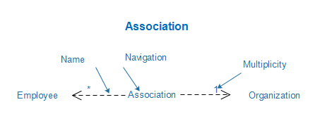
Association

It describes how many elements are there in an association and how they are interacted. 


Generalization

In simple words it is parent child relationship.It describes the inheritence relationship between elements.


Extensibility

Extensibility is like a mechannism of extending its capabilities like syntax etc:. There are three (3) main mechanism of extending.

  • Stereo types - Represents new elements
  • Tagged values - Represents new attributes
  • Contraints - Represents boundaries


Saturday, April 11, 2015

CHAPTER - 3 [ UML Modeling types ]


  • There are static/stable features in your system and Structural model captures those stable features.
  • Behavioral model describes the interaction among structural diagrams.
  • Architectural model consists of both structural and behavioral modelings and it represents the overall framework of the system.

CHAPTER - 2 [ UML Building blocks ]


This chapter will discuss about UML Building blocks. Basically it consists of 3 components namely,


1.Things.

2.Relationship.

2.Diagrams.


1.Things

This is the most important part in UML building blocks. Things can be classified as,


  • Structural
  • Behavior
  • Grouping
  • Annotation


Structural.


Structural things define the stable (static) part of the model. Structural things are class, Interface, collaboration,use-case,component and node.

*Classes are set of objectives which gave similar responsibilities.


*Interfaces are set of operations which specify set of classes.


*Collaborations defines connections between elements.

*Use-case describes set of actions performed in a system.


*Components describes the physical parts of the system.


*Nodes describes a physical element which has a run time.


Behavior.

Consists of all the dynamic parts of the system.

*Interaction.

Behavior that consists of a group of messages exchanged among elements.


*State machine.

State machine can show the different states of an entity also how an entity responds to various events by changing from one state to another.

Grouping.

It is a mechanism to group the elements of UML model.

*Package.

Package is the only one grouping thing available for gathering structural and behavioral things.


Annotation.

Annotations are used to capture remarks, descriptions and comments of UML model elements.


2.Relationship

Relationships will show how elements are connected and associated with each other. There are four (4) types of relationships available.

  • Dependency.
  • Association.
  • Generalization.
  • Realization.
Dependency

Relationship between 2 things and change in one element affects the other.


Association

Set of links that connect elements of UML. It describes how many objects are participating in a particular relationship.


Generalization

Connects a specialized element with a generalized element.


Realization

One element describes some responsibility which is not implemented yet.


3.UML Diagrams

This is the core of UML modelling. The various types of UML diagrams are,

  • Class diagram.
  • Object diagram.
  • Use-case diagram.
  • Sequence diagram.
  • Component diagram.
  • Activity diagram.
  • State-chart diagram.
  • Collaboration diagram.
  • Deployment diagram

Thursday, April 9, 2015

CHAPTER - 1 [ Introduction to UML ]

Why UML ?

UML (Unified Modelling Language) is a standard language to specify, construct and document software systems. It is a way of picturing the software blueprints and it is completely different from languages like C++, Java etc: UML is not developed only for developers but ones who need to understand the business scenarios or the system is also can get used to UML. And the most important thing is, UML is not only for software projects but also for other projects as well.

Let's look at a real life example to understand the importance of UML. 
You are constructing a building. A single block building. So the architect designs the pattern and the builders use it to construct the building (blue print).It is the way that the architect and the builder communicate with each other. More the building is complex there is a higher complexity in communication between the architect and the builder.

Designing a software is not that easy. It is more complicated than constructing a building because ones who are involved in designing a software need to have critical communications among each other.So UML has emerged as a software blueprint language for analysts, designers and programmers because it addresses all types of above users.

The most important thing is UML is applicable to Object Oriented Problem solving.


Object Oriented Problem Solving (OOP)

Object Oriented Concept is a programming paradigm based on the concept of "Object".They are data structures which consists of data, fields (attributes) which have procedures.

Object Oriented Concepts

  • Object
  • Class
  • Abstraction
  • Encapsulation
  • Inheritance
  • Polymorphism

Object- An object represents an entity.

Class-Blue print of the object.

Abstraction-Behavior of the real world entity.

Encapsulation-Mechanism of binding data together.

Inheritance-Making new classes from an existing class.

Polymorphism-Mechanism to exists in different forms.